Sunday, February 22, 2015

Using shift registers in Arduino projects

If  you are using an Arduino board(like Uno) you get about 12 digital pins for your projects .this number is fairly enough if your  project is a simple one that won’t consume no more than few pins but as the complexity of your projects increase soon you will run out of pins. There are few solutions for this.
  • You can buy a board like mega and expand your number of digital I/O pins.
  • You can use multiplexing/ demultiplexing chips to read and write to pins.
  • You can use shift register chips to expand the I/O pins.

It’s obvious that the first solution shouldn't be your first choice since it will cost you few bucks and it’s probably is not the best solution as well. Eventually you will run out the pins if your project needs more than 54 digital I/O pins .So keep that option ,optional!!!.

Today I’m going to discuss about the 3rd solution I mentioned. I will discuss the 2nd (mux and demux) solution in future when I get a chance. Shift registers are used to expand the I/O capabilities in an electronic circuit. In Arduino domain using only 3 pins of the board and a single chip you will be able to control up to 8 outputs. And by cascading the shift registers you will be able to control thousands of outputs only using 3 arduino pins. In order to do this I have used 74HC595N chip which has 8 outputs. For this instance I used 3 595 chips to control 24 LEDs.

Figure1 74HC595 chip


Figure2-Pin configuration


Q0-Q7   are the output pins that connected to LEDs anode.74HC595 is capable of sourcing current to               LEDs  but there are different chips that use sinking current(current is drawn into the chip)                  method to drive LED. So make sure you check the data sheet if you are not using this chip.

VCC/GND   +5v supply and ground.

DS   serial data input to the chip. This pin is connected to one of the digital output pins in Arduino              and if you cascade several of them, you have to connect the DS pin of the second chip to the                Q7’ pin of the first chip.

OE      output enable .the horizontal piece of line indicates that it’s active low. That means you                      have to make the pin low in order to make the output enabled. So connect that to the                           ground to make that pin low .

ST_CP   storage register clock input .this pin is also called latch pin since it’s the pin that is used to                  transfer the data stored in the chip to the output pins. The value loaded into the chip won’t                    get pass through unless this pin gets a LOW to HIGH transition.

SH_CP  shift register clock input. This pin is used to insert the serial data into the chip register.                         When the pin’s state gets a transition from LOW to HIGH it reads the value of the DS pin                  and sends the value to register.


MR         Master reset.(active low )this pin can reset the whole chip when activated. The values                         stored in the chip will be erased .So connect this pin to +5v supply to avoid resetting the                       chip.

Q7’         This pin is used to cascade several chips together and further expand the outputs.
               Please read the data sheet I provide carefully to understand the functionality and the                            autonomy of the chip better.   And also I have add some links to some youtube videos  that I               referred in order to learn about shift registers. I highly recommend you to watch them to get                 more understanding how this chip works.

Writing the program

There is a function called shiftOut() defined in Arduino to use in shift registers but I will present you another way of implementing the functionality and later I’ll give the code I wrote using shiftOut() function. As a first instance we’ll look how to implement a single shift register.  Use the above diagram to construct the circuit. If you want you may avoid the 1uF capacitor ,it is used to remove the flickering .

Figure3-Circuit Diagram 


Now we’ll look at the code. I have attached the source file at the end of the post. So you  may have a  look at it or you can use it in your project.

Figure4-Initializing code


Initialising is done as usual in first place. In there I have assigned pins 8,9 and 10 to the serial data pin, clock pin and latch pin of the chip. And also I created an array consists of 24 elements in order to store the status of each LED. It’s type is Boolean ,therefore I can store a HIGH or  LOW  value in each element. time_const  is used to control the speed of the LED on and off. Writereg()  is a function which defined to shift the data into the chip.


Figure5-Writereg() function


At the beginning of the function the latch pin is set to low and at the end (when the data has been transferred to the chip) it is set to high. In that way we can give a LOW to HIGH transition and data has been sent to output pins. As I mentioned  above the clock pin is used to distinguish between data bits .First the clock pin set to low then the data bit is sent to a storage register in the chip .and again clock pin is set to high and this transition stores the bit in storage register this happens in all 3 chips. The first 8 bits stored in the chip which connected directly to the Arduino. When we moved the next  byte to the first chip the previous byte get shifted to the next shift register .Like that we can shift any amount of bytes as long as we have enough chips and the first byte that shifted will be stored in the last shift register that cascaded.  

Using shiftout() function in sketches 


Arduino community has provided a built in function to handle shift functions easily.

Syntax

Shiftout(Data pin,clock pin,bitorder,value)

Data pin -  serial data input  pin of the chip is assigned to this pin.
Clock pin – SHCP pin of the chip is assigned to the this pin.
Bitorder- For this you can assign two values. They are MSBFRIST or MSBLAST .

MSBFIRST 

setup the least significant bit of the value you pass to Q0 pin. For example if you send value 6       (110 in binary) to the shift register, it will be represented as follows,

Q0 – 0
Q1 – 1
Q2 –  1 

LSBFIRST 

This is the opposite of MSBFIRST ,it will assign the LSB bit to Q7 pin and  MSB bit to Q0.

 Most of the time we are only going to use MSBFIRST since it’s much convenient .So if something is not displayed as you wish when you are executing the code try replace MSB with LSB or LSB to MSB that might solve the problem. There is a tutorial in Arduino site that explains this function in more details. Please read that as well.
Shift registers are very useful way to expand the I/O capabilities of your microcontroller. I found about this technique when I was looking for a way to control a LCD display by Arduino without compromising 6 pins. I haven’t tried it yet but I hope to write another about that in some other time. Please use the links I provide below to get to know more about shift registers.

Links


following links are few tutorials I referred in order to learn Shift registers.


Tuesday, January 6, 2015

Convert your car –rear view screen to a monitor for Pi

If you wanted to make your cute ,credit card sized computer to something more adorable all you need is a small display like the one in the picture above. So from today’s post ‘m going to share with you about how I did that.
Things you are going to need:
  • A Raspberry Pi computer.(I’m using a model B one)
  • Car –rear view monitor which has PAL/NTSC connection
  • A RCA coupler male to male
  • 12V power supply for the monitor.(1A output  will be all right but check the monitor specification first)
Car-view monitor

RCA male to male adapter


 You can buy the monitor in the above picture for 26 US dollars by Ali express web site.  It’s the cheapest one could find and it worth for it’s price and also shipping is free but if you want a monitor with HD facilities and if you can afford around 80 US dollars or more then check out the Adafriut official site. They got some really good monitors for the job.
You can buy the RCA male to male adapters in Ebay ,I bought that by core electronics and it cost me only around 2 US dollars excluding shipping. I could complete the project under small budget around 30 US dollars since I had a suitable power supply .If you have any electronic device which uses a power adapter you might be able use that as the power supply for the monitor. The adapter I’m using is a power supply to an unwanted router.
In this tutorial I assume you already have a working pi and you are familiar with using terminal or any other text editor to edit text files.
First connect the monitor to the yellow RCA jack using the RCA male to male coupler. Connect the power  adapter to the monitor and turn on the pi. If the display is not showing anything try to switch to NTSC /PAL mode by pressing 3 or 4 in the keyboard. if you can get a signal to the monitor then it should be very small and hard to read. We need to change the resolution for  a better view and  it can be done by editing a file called config.txt .My display is compatible with 800*480 and 480 *272 resolution and try to choose the smaller one since it will display the text more clearly. But you can use other values for these if they are agree with your screen ratio. For example if your screen ratio is 16:9 and your width is 520 pixels then you can calculate the number of pixels for  height  (520*9)/16 = 293   pixels. You can find the optimized resolution for the display by trying few values like these.

In order to change the settings type the following command in the terminal .

Sudo vi /boot/config.txt

This command will open the config.txt file to edit . In the file find the following lines. Before you edit anything I recommend to keep a backup of the file.

#framebuffer_width=1280
#framebuffer_height=720

  These settings force the display to set the resolution to the given values and to activate them remove the comments and amend the value to the values you want for example like the following,
framebuffer_width=480
framebuffer_height=272
After editing these lines save (Shift+z and wq) and reboot the pi (sudo  /sbin/shutdown –r now).You can see the display is bigger and more readable than last time.but most of the time there will be some unused space(pixels) in the display and we can stretch the window until the unused space is gone. You can optimize the display by this. To do this open the same file(config.txt) and find the following lines ;

# overscan_left=26
# overscan_right=26
# overscan_top=16
# overscan_bottom=16

Remove the comment sign and change the values to negative values in order to expand the display. You can use values up to -30 , values beyond that didn't work for me .After that save and reboot the  pi. You might have to repeat the above steps few times in order to get the best output. It’s all about trial and error. Besides these settings you can do more configurations using this file. Read the file carefully to know what you can do with it, try to play around. If everything went well you will get a nice display like in the pictures.  


Friday, December 26, 2014

Introduction to robotics -3(Writing the program)

In the previous post I pointed out some of the key things about the hardware components and software techniques that I used to construct the robot. I this post I hope to give more insight into the software perspective of the design.(I assume you have read the previous article and the links I provided . )

In this project my main concern was on to the software side since most of the hardware I used was either simple or they are already on a working phase (like Arduino and the chassis.)Anyway before you write your software it’s important to realise what sort of functionality you are expecting from the robot and break it down to simpler objectives. In my case the functionality of the robot can be brake down into several steps.

  1. Moving the robot to forward, backward, left and right.
  2. Detect an obstacle in the path.
  3. React to the obstacle by turning to a different direction.
  4. Continuing moving along the new direction until it encounters another obstacle.

To achieve the above tasks I used a simple program which is written using Arduino IDE. Here is a simple flowchart which summaries what the program does. The 15cm boundary is an arbitrary value, you can use any value which is in the sensor’s detection range. but I recommend  small values since the sensor is not very accurate in long distances. Initialise is the process of feeding the program and the controller about the necessary settings like the I/O pins used the constants, Interrupts etc.. I’ll explain this when I get to the actual program. The delay function which I used in the program does very important task and I would like to explain the importance of that. It’s a fact that mechanical systems are always slower than electronic systems when responding. So there will be a delay when you send an electrical signal to a mechanical system to do something and actually starting to do that thing. It won’t complete that command instantly .So a delay is needed between two commands to complete each. Otherwise your system will act in unpredictable ways. You should keep this in mind when programming since it’s not straightforward. It’s one of the most important thing s I learned in my uni. You can use any amount of delay time .with some trial and error you can easily find the most suitable delay time.

Initialise

As I mentioned above initialisations prepares the system and the program for the execution. It basically consists of declaring the I/O pins, variables  and interrupts. there is a separate function called Setup() to initialise the system. Outside this you can declare the functions you are going use and any #define statements. I have used timer interrupts to trigger the sensor every 50ms and take a distance measurement. So I strongly recommend you to read the article about the interrupts or you can just copy the code of mine. It’s a must to know how to tackle interrupts in embedded systems , otherwise your programs are not going to be function efficiently. If you want to change the trigger time all you have to do is to change the value of OCR1A to a value you desire within it’s range. Besides this you have to include two libraries which handle interrupts in setup().

Figure1-Flow chart


 Moving the robot

Moving the robot in a particular direction is one of the primary task in any robotic project .So first of all I wrote a simple program to check the movement of the robot and to verify my hardware is working as I expected, especially the H-bridge control circuit. To achieve this I used 5 functions that each set the pins connected to the DC motors in a particular configuration. ( by setting these pins high or low you can control the direction and rotation of the motors.). I declared them as void since we don’t need that function to return anything .
Figure2-An example for control function 


This pin configuration can be unique or not but play with your motors to figure it out. But keep in mind not to put all the pins in HIGH since it will damage the IC. It’s always encouraged to use separate functions to carry out different tasks and not to do everything in the main() function. This practice is important when the program gets complex and branched. The functionality of the main() is like the functionality of a leader in a team. A leader is not there to do everything by himself but rather to coordinate others to do what they are capable of. Like that by separating different functions it gets easy when debugging and finding  errors.
Besides that there are two other functions to measure the distance and to trigger the sensor every 50 ms . When using interrupts there is a common practice to declare the variables used in ISR to be declared as volatile. The reason for this is to indicate to the compiler that variable can be changed a synchronically to main since it gets updated by the ISR. if you don’t declare the variable as a volatile type the variable might not get updated correctly .So it’s an important aspect to remember.


Figure3-Distance measure function


Distance value is in cm and you can change this by changing the constant 29.1 but I think cm is a reasonable range for the robot. I used a delay  of 1ms to get some time for the sound wave to spread out and reflect back into the sensor. I used unsinged int as the return type of the function since a distance can only be a positive value but recently I came to know that it’s recommended to not to use unsigned number types in practice since it might causes some troubles if you try to do arithmetic with that. Since  I don’t do any mathematical operation to  it seems legit to use it.    

Figure4-ISR function                      


This ISR function is a defined function. So all I did was to write the content of the ISR. So when the timer interrupt is triggered it will execute the Measure _distance() function and update the variable x which holds the distance value.

Figure5-Configuring Timer 1                                


I highly recommend to read this article to understand the above configuration settings .It’s really important to understand how interrupts works in order to create good designs. If you would like to use that configuration without any change it’s ok but if you want a different time (this is set to trigger every 50ms) you can change the value in 0CR1A register. For example if you double the value (780*2=1560) interrupt will trigger every 100ms.
Although this was a simple design I learned lot of things...and above all I had a chance to put the knowledge I gained in my studies to build something really works. That’s was a great experience for me.
There are some cons in the design that I would like to discuss in here.

  • Sometimes the robot’s behaviour gets unpredictable and it fails to spot an obstacle and gets hit. My primary suspicion was it was due to a fault in sensor since it only happened few times. and sometimes it stopped moving  for no apparent reason. As s solution I changed the location of the sensor to a centre position and it improved the performance of the robot.
  • According to the Figure1, when the robot detects an obstacle it only turn to right side. It’s not a very intelligent behaviour .Therefore I wrote another sketch to improve the ability to decide a direction to go when it encountered an obstacle. I’ll give you that in the next post.

You can download the complete sketch  for the project and play with that around .but I highly encourage you to write your own sketches since it will improve your programming skills .I will give a detailed information about the improvements I have done to the design in the next post.

Below are few photos of my robot Walt...


Saturday, December 13, 2014

An Introduction to robotics-2

In previous post I talked about some background information about what kind of things you have to consider when planning to build a robot. In this post I’m going to extend that to another prospective. I’m going  to give you some very simple but useful information about several things you want to know about basic electronics and programming in general. and also I assume the reader has at least some basic knowledge in C programming and how to use Arduino IDE and other associated softwares.

As I told earlier it’s easy to design a robot(or any other design) if we breakdown the whole thing into several pieces and designing each one carefully. There are few advantages of this approach.

  • You will have a good understanding about each section and how they all fit together in a much larger system and the functionality of each section.


  • When something goes wrong (believe me it will) you don’t have to check each and every part, just the part associated with the fault, it will narrow down your scope and saves some time.

  • You can reuse what you have done in a project in another project if it’s suits with the requirements. It will save your effort since you don’t need to do everything from scratch .  Ex: if you wrote a function to compare two input values and send the result to main function rather than doing everything in the main, you will be able to use that function in some other instance with fewer or no changes.


  • Take your time to design and think about what you are going to do before you are actually going to do it. Thinking is one of the most important things in building something. It will help you to save your time, money and effort.


Some thoughts on embedded system programming 

There is no huge difference between writing a program to a PC and for a microcontroller .but there are few yet very important aspects that you have to remember when writing programs to a microcontroller.

  • Microcontrollers have very limited amount  of resources(memory and processing power)to work with. Therefore you have to be very careful about the size of your program and the memory it’s going to use during the execution.


  • Most of the time you will be using C or a derivation of C to program. Therefore it’s a good thing that you are comfortable with using C as a language. C is wildly use in embedded systems because it’s a well structured and easy to learn language. If you are a working most of your time in high level languages you might feel C is very low level language but that’s the thing what makes C is very suitable for system programming.

 
In this first project I didn't use much complicated things but I think there is a concept that you have to be familiar with, Interrupts. Interrupts are one of the fundamental things in embedded   environment. An interrupt is simply an asynchronous process with respect to a main program which is used to get information to the microcontroller from outside world or within the system. There are 2 types of interrupts.

  • Hardware interrupts
  • Timer interrupts


A signal from a push button press is an example for a Hardware interrupts and sending a pulse to the system using a clock provided to indicate something to the system is an example for a time interrupt. As I said interrupt is a technique used to get inputs into a system. There is another way to do this .It’s called polling. Checking for an input within the main program constantly is called polling. Using interrupts have a significant advantage over polling in embedded system because interrupts are asynchronous .Interrupts can happen anywhere within your main and you don’t need to worry about that once you set up an ISR (Interrupt Service Routine) to handle that interrupt. I’ll provide some links where the reader can get more information about interrupts . It’s very important to understand the role of interrupts and how to use them effectively in programming.

Electronics  used in the project

Since I’m using Arduino as my control system(Brain) to the robot it made lot of things easy for me. Although I didn’t want to worry about building a system from scratch there was a big constrain . Arduino is a good platform for robotics but it cannot provide enough current to drive heavy loads like DC motors. It’s maximum output current is 40mA and voltage is +5V.So I had to think about a way to drive 2 DC motors without destroying my Uno board. In electronics it’s done by using a H-bridge circuit. A H- bridge consists of MOSFET transistors that can control both speed and direction of the motors. I used a L293D chip to control the motors.   There are motor driver shield that can drive upto 4 DC motors but the price was too high for me and also I needed only one  since an IC can control 2 DC motors and it costs me only 3.95 AUD. You can easily purchase these type of  IC in web cheaper.


L293D IC


Pin configuration of the IC


  • Voltage range : According to the datasheet L293D can output   4.5V to 36V.My motors working voltage is around 7.2V.there for it’s ok to use this chip.

  • Output current is 600mA and maximum output current is 1.2A. My motors draw 450mA(each) in normal operation and the stall current is about 1.17A.So The IC can drive these 2 motors without much trouble.


This is a great video I followed to get this thing work. I’ll explain more about the chip when required. 

 Pin description of the IC

Enable 1,2 – These pins control the motors. If they are  high motors work ,if they are low motors are   disabled. Connect these pins to +5V pin in the Uno  board for this project.

GND – Simply connect these 4 pins to ground of the Uno .

Vss  - Power supply to the chip.(+5V).  
             
Vs  -  Power input to the motors. You can connect your battery output to this pin.                                                       
Input 1,2 – These are used to control the motor1.by setting pins like High, Low or Low, High you can change the rotation direction of the motor. Never set both pins in High as it will damage the chip. Setting both pins low will turn off the motor.

Input 3,4 – These are used to control motor2.Same functionality as Input 1,2.

Output 1,2 and 3,4 – These 4 pins connects to the motor 1 and 2.


Sensors

HC-SR04 Sensor-Pins from left-VCC,Trig,Echo and GND

 I used a conventional HC-SR04 ultrasonic sensor as my sensor to detect the obstacles and send that measured value to the microcontroller. All you have to know is that this module sends out an HF wave and by detecting a reflected wave t can calculate the distance. Obviously You have to write a program to do so. In my experience these are good to detect things that are away up to 80cm after that it might give you wrong readings but since it’s very cheap  it’s very good sensor for a simple robot project.

Pin description of the sensor


VCC – power input to the pin (+5V)

GND – connects to the ground pin of the Uno.

Trig -  Setting this pin high will emit a HF wave from the sensor.

Echo – When the sensor detects an HF wave it sets this pin to high and by using a function called pulseIn() we can find out the time taken by a wave to return to the sensor. This value is in milliseconds and it has to be divided by 2 in order to get the value for the time taken by the wave to reach to the obstacle from sensor.

So these are some things that I believe you have to be familiar in order to build a simple robot. I’m not going give you every detail about how I built my robot since it’s inappropriate and you can use these guidelines to design your own robot. In the next 2 posts I hope to discuss more on the structure of the programs I wrote for the robot. 

Picture of my robot-Walt


Further Readings

Please refer to these websites and documents to improve your knowledge.


Tuesday, December 9, 2014

An introduction to robotics

It’s a pleasure to be here after a while. I’m having my summer vacation after a long, stressful but exciting semester and I’m hoping to spend my vacation studying robotics and microcontrollers with my knowledge I gained throughout the semester. So I thought to share some of my experiences about planning and building simple yet very exciting robotic projects I've done so far.

Building a robot by your self could be a challenge. It depends on how complex your robot project is. But it’s rewarding. You’ll get to know a lot about electronics and programming and it’s a great chance to use your knowledge to building something cool if you already have some academic background in electronics and programming. I’m expecting to write few blog articles about how I carried out my projects and in this article I’m hoping to present some basic ideas about robotics and design. Please use the links I’m providing throughout the article to expand your knowledge. 


First thing first

When we are  planning to build a robot we need to have an idea about what sort of robot  we need or the requirements .In my case I wanted to build an obstacle avoiding robot which is capable of detecting obstacles ,avoid them as much as possible and wander around in a given area. Next step would be searching for different examples in web and have an idea about how those types of robot functions, what sort of materials they have use to build the robot  and what is it capable of. There are lots of  very good websites in the web which were very helpful in my case. As well as these ,you need to be aware of your budget .If you are a student like me you won’t be able afford much to building a robot but it’s good to have at least few hundred dollars if you wish to buy some materials for your robot.


Modelling your robot

Every robot can be simplified into four simpler sections.
  • Sensors, Inputs and outputs
  • Control system
  • A Power Source for robot
  • mechanical parts

The combination of all these sections makes pretty much every robot we see. So when planning it’s much easier and efficient to break your model into these categories and find the most suitable parts for your application.

Power source

The main power source for  a robot will be batteries .Things like solar panel will be a good idea if your robot will spend much of it’s time out door but even in that case batteries will be there as a backup power source. So it’s good to do some research about types of batteries used in robotics before you start. The article in here is a good article about different types of batteries and what are the pros and cons of them.  Rechargeable batteries are a good option if you can afford them since they are a bit expensive and you might need a purchase a specially designed battery charger along with them but if you are hoping to continue your robotics consider it as a good investment. In general you may be able to find good deals in E Bay or Amazon  if you search them a bit. Currently I’m using 6 conventional AA size batteries (1.5V) and a 9V battery as the power source for my robot  and I’m ok with them since I’m not extensively using my design.

Sensors ,Inputs and outputs


Sensors are another important part of any robot since they are the only way your robot can get to know it’s surroundings. There can be many types but some simple common sensors would be IR sensors, ultra sound distance sensor , photo resistors and thermal sensitive transistors etc. By  utilizing these you can give the robot an idea about it’s surroundings and to respond to them accordingly. In here I used an ultrasound distance sensor (HC-SR04) to measure the distance and navigate the robot. Your outputs would be LEDs, Speakers or even LCD displays which are capable of inform something to you about the status of your robot.
Image retrieved by http://blog.oscarliang.net/how-to-use-ultra-sonic-sensor-arduino-hc-sr04/

A Control system


For most of us this would be the first thing comes in to mind when we talk about robots .Controls system acts like the brain of the robot. It takes the inputs from sensors ,process them according to the instructions given  by the program and decide what do according to the results and sends the control signals to the required hardware.There are lots of microcontrollers you can choose to program your robot .Arduino is one of the most popular platform for robotic applications and I’m using that an Arduino Uno board to control my robot .It’s considered as one of the best platforms for the beginners and it’s a pretty decent and sufficient board for most of the robots applications. It is capable of many functionalities that you can use to control a robot and there are lots of support for Arduino projects out there in web and it’s very helpful when you got a problem or trying out new things and you need some support. I highly recommend official Arduino web site as a reference.

Image retrieved by http://store.arduino.cc

All other mechanical and electrical components


This categorises all other moving and non moving parts like the chassis , electrical motors connectors wheels etc. I’m not going to this section in detail about these as my primary concern is electronic and software section of the robot and I don’t have much knowledge about the mechanical parts or how they work. So my solution to this was to buy an assembled chassis from web and all I have to do was design electronics (both hardware and software)to control the motors . I used a tank type chassis (RP5-CH02) as the base of my robot because it got all the motors and gear systems that otherwise I have to build. So it’s completely up to you to make a decision but if you can build a chassis ,then you will have more freedom to customize your design.  
 
Image retrieved by http://static.rapidonline.com


So in my next post I’m hoping to talk about some of the things you may need to know about  electronics and software fields to make a robot.    

Thursday, September 4, 2014

Parallel Computing


“Parallel computing is a method of computation in which multiple calculations are carried out simultaneously” (Wikipedia). Although parallel computing was initially restricted to high performance computing, physical constraints like heat dissipation has meant that the interest in parallel computing is now across all computing disciplines including personal and mobile computing.


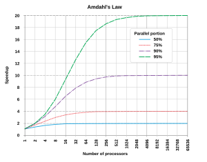
By parallelizing the computation, it is expected that the workload on any given processing unit is smaller thus avoiding hitting physical constraints in processors architectures. Also by employing multiple processors for the same job, it is also expected that the job gets completed quicker. However the benefit of parallel execution on execution speed is constraints by Amdhals law. Amdhals law states that the “Speedup of a program using multiple processors is limited by the time needed for the sequential fraction of the programme” (Wikipedia). This law is quite important for the industry to realise that not all the problems are benefited by solving them under parallel computations.


(Amdhals law, Image retrieved: Wikipedia - http://upload.wikimedia.org/wikipedia/commons/thumb/e/ea/AmdahlsLaw.svg/300px-AmdahlsLaw.svg.png)


Computing parallelism is achieved at different levels starting at bit level and going on to instruction level, processor core level and machine level. Bit level parallelism is easily identifiable by the existence of 32 bit and 64 bit operating systems. Increase in bit level parallelism enables the processor to complete computations with less number of instructions.

On the other hand instruction level parallelism enables the processor to have a larger instruction pipeline. A larger instruction pipeline will mean that at any given moment the processor can process multiple instructions that require different kinds of operations.

When computer processors reached speeds closed to 3GHz, it started getting close to physical limitations, specially respect to unmanageable heat dissipation. Rather than trying to increase the frequency of a single processor the industry came up with the multi-core processor design where each processor runs close to 2.5GHz. There are designs that also treat the graphical processing unit (GPU) as an additional processor thus increasing the internal computer parallelism even more. These innovations have begun to reach mobile devices as well (Most new smart phones have multi-core processors)

There is also multiple method of parallel computing achieved by combining large number of computing units (machines, processors etc…) together. Distributed computing, cluster computing, massively parallel computing (MPP) or grid computing are some of these where each one differs from the other based on their architectural differences.


Google is a great example of huge commercial cluster computing unit. Although its details are not publicly available information it’s one of the largest ISPs in the world. The beauty of its cluster is the usage of general purpose Linux computers to cater for ~60k search queries Google gets each second (http://www.statisticbrain.com/google-searches/). Most of the large social computing platforms like Facebook and Twitter are using the same technique to cater increasingly large amount of computation they have to perform.

Parallel computing challenges computers scientists with a different set of problems like state management, race conditions and orchestration. It’s also generally accepted the programming for parallelism is harder and less efficient than sequential programmes, although this could well be due to the fact that current programming landscape is built on years of development in sequential thinking. Programming languages like Scala, F# and Haskell are working hard to make programming for parallelism more intuitive and productive.

Parallel computing may well have more innovation in the pipeline and holds a huge promise towards the evolution of computing in general. It has contributed immensely to both hardware engineering (Processor manufacturing, networks) and software engineering practices.

Sunday, July 27, 2014

Mobile Computing

If you haven’t read my previous article about internet and Pc, please read it here.

(Image retrieved from: http://www.globalgrind.com)

Wikipedia defines Mobile Computing as “Human Computer Interaction by which the computer is expected to be transported during normal usage”. While the PC started taking computing machines to everyday consumer, mobile computing has really infiltrated average consumer market and revolutionized computing as a whole. Mobile computing is spreading faster than any other consumer technology in history. It has opened up new possibilities for human interaction by enabling the continuation of the computing experience regardless of geographical location. Smart phones have revolutionized not just computing but society as a whole since it’s ability to connect people in a very convenient and personal way.

Mobile computing is mainly delivered at present via smart phones and tablets; however it applies equally to PDAs, in vehicle computers, electronic readers, wearable computers etc...At present the mobile computing market is divided in to 3 main platforms namely Apple iOS, Google Android and Microsoft Windows.

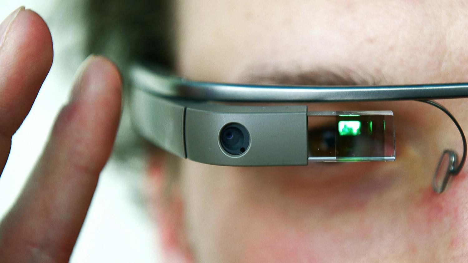
Innovation in mobile computing can be categorised in to hardware, software and process. Hardware innovations can be seen around areas such as device power management, touch screens, material design for portability etc… An everyday smart watch at present is deemed to packs more computing power than the super computers that took Apollo 11 to the moon. This feat is mainly due to innovations in engineering practices such as materials, electronics and design powered by sheer competitive nature of the market. Devices on the brink of mass scale usage such as Google Glass and Agent smart watch will continue to expand the boundaries of mobile hardware technologies.


Although initial focus on mobile computing was mainly around its hardware, an increasing amount of attention is give to Software. Whole new software areas like mobile apps, location aware programming, and inter-device communication are developing every day thanks to the population of mobile computing. The open nature of the platforms enabling anyone with right skills to build and distribute software for mobile devices has feed the exponential adaptation of mobile computing among general public. 

Another aspect of mobile computing is its contributions to engineering and management practices such as industrial design, supply chain management and mass scale production/distribution. Global companies like Apple or Samsung are heavily dependent on a highly optimized and synchronized set of engineering and management processes to churn out quality devices in millions each day.

 Mobile computing posses its own engineering and social challenges like security, privacy, inconsistent connectivity, potential health hazards and quality of interaction. Regardless of these challenges mobile computing is expected to play a major role in the future of computing.